Enrique Alvarez
[All actions taken based on the information provided here are at your own risk, and I am not liable for any damages or consequences that may occur. Please exercise caution and seek professional advice as needed]As a dedicated bonsai enthusiast, ensuring the well-being of your bonsais is always your top priority, and water quality plays a crucial role in this endeavor. Unfortunately, in my specific location, the water quality leaves much to be desired, with TDS values reaching approximately 391 ppm and a high pH level of 9.14. The most concerning aspect is the elevated salt content, particularly sodium, which measures at 65 ppm. These factors have been impacting the health of my precious bonsai trees negatively.
Recently, after attending a meaningful bonsai event in MN, I had a revelation – the key to achieving happier and healthier bonsais lies in gaining better control over their water supply. One promising option is to collect rainwater, which offers numerous benefits. However, this approach comes with its challenges, especially if you have a substantial bonsai collection. Acquiring a sufficiently large container to store the collected rainwater becomes necessary, and relying solely on the weather to replenish this source can be unpredictable. Insufficient rainfall may lead to water scarcity, putting your precious trees at risk.
Given these considerations, finding an alternative water management solution has become imperative. Exploring various options that would enable me to consistently provide optimal water conditions for my beloved bonsais is now my primary focus. By proactively addressing this crucial aspect, I was determined to ensure the thriving health and beauty of my bonsai collection for years to come.
I devised my own innovative design for an automatic Reverse Osmosis (RO) system, which I hope could be highly beneficial for our community members. This system utilizes the standard water pressure found in households to effectively remove the majority of minerals, both harmful and beneficial, from the water.
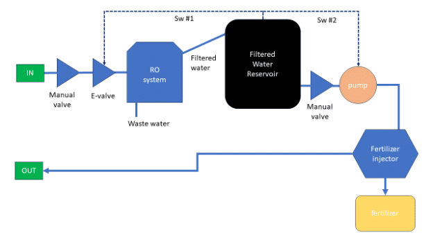
Figure 1. Block diagram of the proposed RO system.
In the proposed system (shown in Fig. 1), the water flows through a series of valves, which act as controls to regulate the water’s flow. Once through the valves, the water is directed into a readily available 4-stage RO system for filtration. This RO system has two outputs: one carries the wastewater with high Total Dissolved Solids (TDS) values, while the other output delivers the filtered water, boasting a TDS reading of approximately 20.
In order to ensure a steady and higher flow rate for irrigation purposes, the filtered water is collected and stored in a reservoir, clearly labeled in black on the system diagram. As RO filters are not known for their rapid filtration, this reservoir system becomes essential to achieve the desired flow rate during irrigation. Within the reservoir’s output, I have integrated an on-demand pump, which is specifically responsible for pumping water out of the reservoir. It only activates when my watering wand is open, ensuring efficient water supply precisely when needed.
Having undergone filtration, the stored water now contains very few to no mineral contents. However, since our trees require specific minerals for healthy growth, this is the opportune moment to introduce beneficial components back into the water. To achieve this, I employ a commercial fertilizer injector, capable of maintaining a controlled 1:100 ratio. This injector effectively pumps and blends the fertilizer with the water in a mechanical manner, ensuring an ideal mix of minerals.
As an engineer, I enjoy incorporating more intricate features to optimize the system’s performance. The initial RO system was relatively simple, providing good water filtration continuously. However, I sought to improve its efficiency and address possible concerns. To achieve this, I introduced several modifications to the setup.
Firstly, I implemented an innovative solution by integrating a sump pump switch with an inflatable design. This switch is strategically positioned to control a motor valve installed at the system’s inlet. Its purpose is to monitor the reservoir’s water level actively. When the reservoir reaches its capacity, the sump pump switch will promptly close the inlet, halting the filtration process. This feature prevents overfilling of the reservoir and conserves water, as no additional water needs filtration when the reservoir is full.
Moreover, I took measures to safeguard the system from potential issues that might occur when the water level in the reservoir drops too low. To counteract this, I incorporated a secondary floating switch within the reservoir. This switch serves as a failsafe mechanism to automatically shut down the entire system if the water level within the reservoir diminishes to a critical point. By doing so, it prevents the in-demand pump from running dry, thereby preserving its functionality and longevity.
By implementing these enhancements, the RO system has become more sophisticated, efficient, and reliable. It now offers optimal water filtration while minimizing water wastage and safeguarding the system’s components.
This automatic RO system is designed to efficiently filter water using household water pressure, remove most minerals, and subsequently reintroduce essential minerals through a precise and controlled fertilizer injection process. This system not only conserves water but also provides our plants with the optimal nutrient-rich irrigation they require for thriving growth.
I am thrilled to share this design with our community, hoping it will be beneficial to others. However, I must emphasize that any implementation or use of these improvements is entirely at your own risk. Please exercise caution and consider the potential implications for your future endeavors.
Other similar systems: https://www.youtube.com/watch?v=BU2eROdhC9c
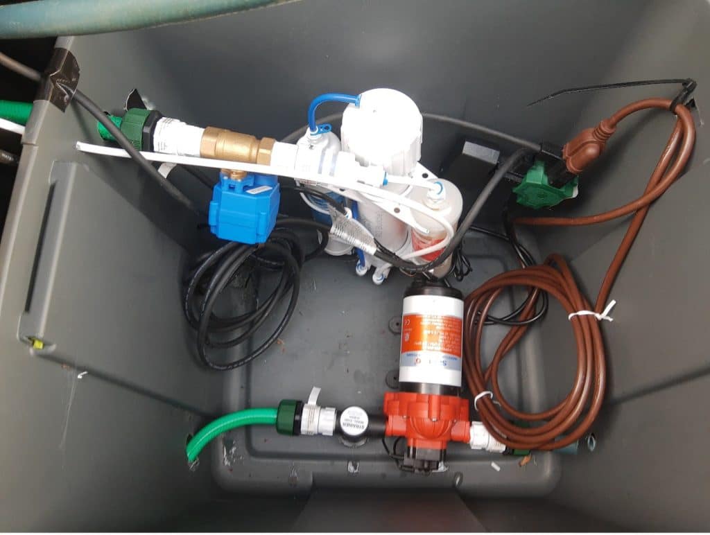
Figure 2. Motorized valve in series with the RO system. We can also see the in-demand pump in the lower section of the photo.
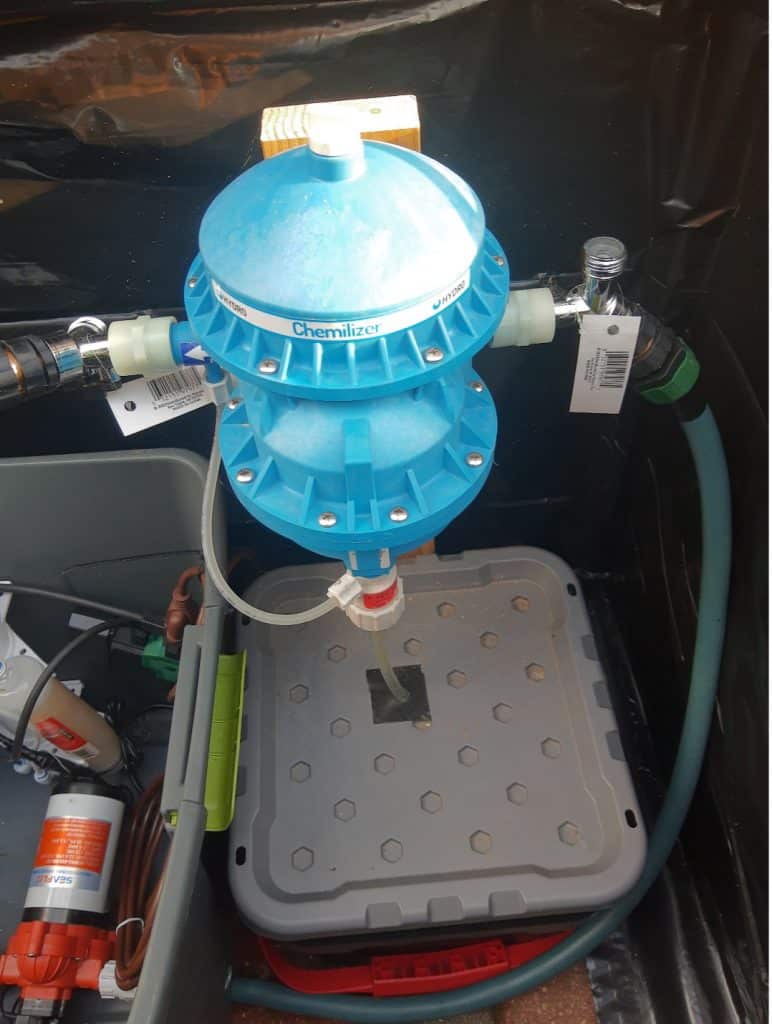
Figure 3. Fertilizer injector. Water comes from the in-demand pump and gets mixed with Dyna-Gro.
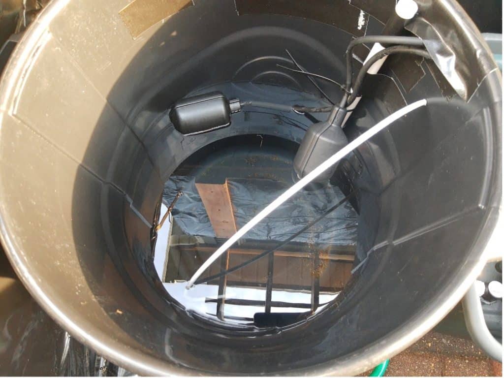
Figure 4. Water reservoir with the 2 float switches.
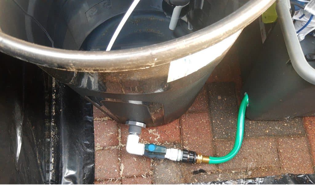
Figure 5. Outlet of the filtered water reservoir.
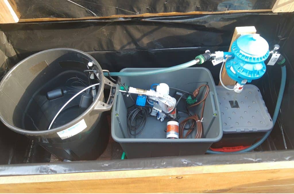
Figure 6. Overview of the entire filtration system.

Figure 7. Outer box to hide the filtration system.